Blended Wing-Body Capstone Project
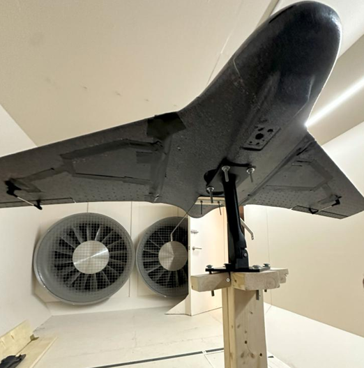
Through the 2024-2025 academic year, I was in a team of 17 members to design, analyse, and build a blended wing-body UAV drone. My personal role was that of the Systems Engineer, with many responsibilities in this interdisciplinary team. Core responsibilities and contributions include:
- Landing gear subsystem constraint identification, global positioning, and sizing
- MLG and NLG design, analysis, and validation
- Steering mechanism design and implentation for the NLG
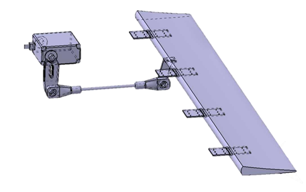
- Control surface integration and actuation
- Assisted heavily with CatiaV5 modelling, including leading the outer mold line reconstruction of the BWB UAV
- Mapping module selection and integration
My work as one of the systems engineers will be described in short below. If you are interested, please feel free to view my final report which contains much more detail.
If you are very interested in the project, my winter design report contains more information regarding LG design selection and the mapping mission. Additionally, my catia modelling practices technical memo and my elevon linkage loads technical memo contain more information into my design methodologies.
Landing Gear
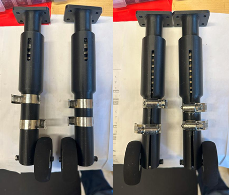
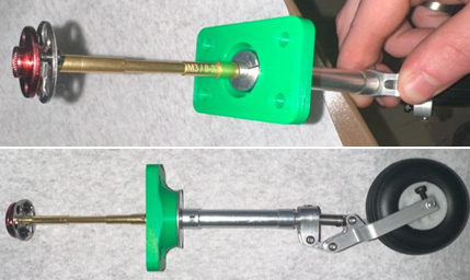
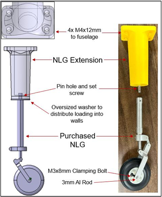
Through the 8-month project, I designed, the main landing gear (MLG) and nose landing gear (NLG) subsystems. The MLG was a completly custom, additively manufactured design, that incorporated an inner and outer cylinder between which a spring was housed. The NLG used an off-the-shelf hobby aircraft oleo strut. An extension was incorporated to maintain propellor clearance.
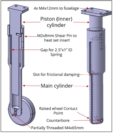
For the shocks of the MLG, a spring with a stiffness of 95 lb/in and a stroke length of 0.59” was selected to adequately engage during typical landings while being capable of further deformation during hard landings. The design of the housing was selected after numerous iterations to facilitate smooth interaction between the piston and main cylinders and be capable of frictional damping to dissapate energy on landing.
Structural Testing
To validate the shock resistance and stroke of the spring upon landing, a drop test was constructed with the help of the Loads Engineer.
Steering System
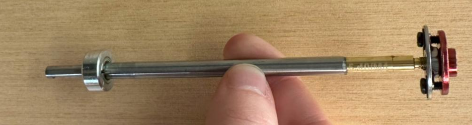
Near the end of the project, a survey of the runway condition and width warranted the need for a steering system to realign the UAV after inevitably hitting bumps in the runway. This system was taken from concept, to CAD, to product in less than 4 days and was successfully implemented before taxi testing.
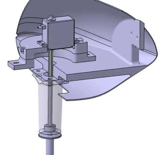
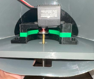
The design used quickly obtainable parts including a D-profile rotary shaft, aluminum servo horns, circular adhesive ready nuts, a shaft collar, and thread adapters, all to transmit servo torque from within the nose of the aircraft linearly to the NLG. To mount the servo within the nose of the aircraft, a modular, variable-height, design was created to facilitate easy reponsitioning of the servo relative to the ground in the event of a under- or over-sized cut on the shaft.
Catia V5 Modelling
Throughout the project I had many opportunities to show competence in CAD modelling.
Outer Mold Line Reconstruction
Although modelling the platform was not originally in the Systems Engineer scope, a terribly broken CAD model of the UAV required additional resources. Having done extensive CAD modelling at Collins Aerospace in Catia, I was appointed to lead the outer mold lines (OML) reconstruction.
The goals and constraints of the project were:
- The geometry of the OML must be preserved
- The model needed to be a completely standalone file with no external references
- Where applicable, dimensions and features should be parameterized to facilitate adjustments at any stage of the development process
Using the source airfoil geometry, the wing was reconstructed from scratch using the Generative Shape Design workbench in Catia. The solid wing was reconstructed with simple boolean operations to remove an internal wing profile from the external wing solid. This thickness of the wingskin was assigned to a variable to facilitate future adjustments.
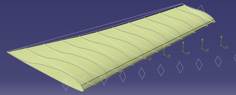
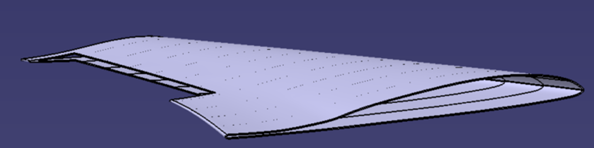
The elevons and winglets were reconstructed similarly to the wing while the fuselage was reconstructed by another member of the team. The reconstruction was essential for many different subteams to continue progress.
- Additive Manufacturing Engineers could adjust various thickness parameters and connections easily for printing
- Provided the fidelity needed for the Aerodynamics Engineer to use it for CFD simulations (described in more detail below)
- Allowed myself to proceed with landing gear and elevon subsystem integration models
- The Masterlines Engineer could continue with weight analyses that fed into flight capability and stability
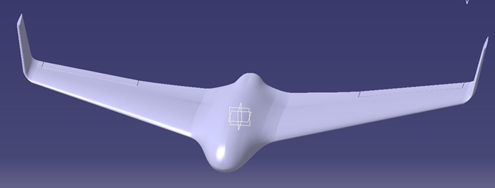
Image Gallery